
How To Choose The Correct Traffic Countdown Timer
A traffic countdown display shows a time associated with a signal phase. The central purchasing question is how that time is obtained from the signal controller. Physical size alone does not establish compatibility, and the display does not replace the primary signal.
Learned cycles
Check whether past phase durations remain predictable.
Trigger input
Confirm how the trigger defines the duration and handles changes.
Controller data
Verify the electrical interface, protocol and fault display.
Learning from previous cycles
A self-learning unit observes earlier signal durations. It may need several cycles before displaying a value, and a programme change may require relearning. The startup sequence depends on the model.
Past cycles do not necessarily predict the time remaining when phases are extended, shortened or called on demand. Confirm what the unit displays when a reliable remaining time is unavailable.

Trigger and communication inputs
A trigger-based unit receives a defined input; a communicating unit receives data from the controller. In both cases, verify how duration is provided and how phase changes are handled. Neither label guarantees compatibility with every actuated or adaptive controller.
RS-485 is an electrical interface, not a universal protocol. Confirm the protocol, data format and supported controller configuration as well as the physical connection.
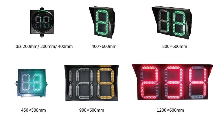
Select the format after confirming compatibility
Confirm the digit arrangement, display range, colour, viewing distance and mounting space for the model. Existing product photographs illustrate different formats; they do not establish mandatory dimensions for any country.
Local rules determine whether and how a countdown may be used. It must not encourage drivers to accelerate or road users to begin an unsafe movement.
Validate before installation
Provide the controller model, operating mode, programme, supply voltage and available interfaces. Request a written compatibility confirmation and the wiring diagram for the exact timer version.
Test startup, programme changes, pedestrian calls where applicable, and communication faults. Do not assume that learning, trigger and communication variants use identical wiring.